Common Info
We offer among the list of most comprehensive lines of specialty Maintenance Absolutely free roller chain solutions available to fi t a broad array of unique application demands. Designers can decide on the series that most effective fi ts the particular requirements on the application. These chains ought to be specifi ed only when conditions prohibit the use of lubricating oil due to the fact, usually, a nicely lubricated normal chain will off er longer life in contrast that has a servicing absolutely free chain. In some applications on the other hand lubrication isn?¡¥t attainable and so the usage of a self lubricated or sealed roller chain is critical.
General Properties of Upkeep Free of charge Roller Chain Merchandise
Sintered Bushed (SL-Series) Chains
Oil impregnated powdered metal sintered bushings release oil on the chain joint as a result of friction designed between the pin and bushing because the chain articulates over 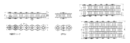 the sprocket teeth. These chains are rollerless and so use thick sectioned powdered metal bushings which could hold a large volume of oil.
PT Type Roller Chains
Oil impregnated powdered metal sintered bushings release oil to your chain joint because of the friction formulated between the pin and bushing since the chain articulates in excess of the sprocket teeth. These chains possess rollers to smooth the action above sprocket teeth. Roller link plates are one particular size thicker to boost power. Side plates and pins have particular coatings to avoid rust.
C-Type Roller Chains
Identical as over except that the side plates are all typical thickness. The power on the CS Style chains is under the PT Sort but better than the SL sort. Attachments with regular dimen-sions can be utilized for this series and as a result they are really frequently utilized on tiny materials dealing with conveyors.
P-Ring Chains
Specifi ed on smaller pitch roller chains O-Ring chains make use of a rubber seal to maintain lubricating grease in whilst stopping the penetration of grime as well as other contaminants to the pin/bush-ing bearing area.
Seal Guard Roller Chains
Specifi ed on larger pitch roller chains Seal Guard chains utilize a stainless steel seal to keep lubricating grease in when avoiding the penetration of filth along with other contaminants to the pin/bushing bearing spot.
Archives
Type 304 Stainless
All parts are produced from AISI Form 304 (18-8) austenitic stainless steel. This materials off ers very good chemical and temperature resistance in a wide variety of varied applications. Simply because Form 304 stainless steel cannot be heat taken care of the mechanical power and put on efficiency is inferior to common carbon steel chains.
Variety 316 Stainless
All components are made from AISI Kind 316 Molybdenum-bearing stainless steel. The molybdenum provides the alloy improved overall corrosion resistance compared with Sort 304 stainless steel specifically larger resistance to pitting and anxiety corrosion cracking during the presence of chlorides. Mechanical strength and wear functionality are equivalent to Sort 304 stainless steel chain.
600 Series Stainless
Pins, bushings and rollers are created from 17-4PH stainless steels which may be age hardened for improved resistance to dress in elongation. The corrosion resistance of this series is very similar (although somewhat inferior) to Sort 304 stainless steel. The operating temperature variety of this material however is additionally not as wide as Variety 304 stainless steel.
Mega Chain:
All parts are produced from AISI Style 304 (18-8) austenitic stainless steel. Obtainable in two versions (Mega Chain and Mega Chain II) which use diff erent bodily confi gurations to get more power that’s related to that of carbon steel chains. The working loads of those chains are superior to that of conventional 304 stainless steel chains due to a higher pin/bushing bearing regions. In addition the two versions possess a unique labyrinth variety seal design and style that aids prevent the penetration of abrasive foreign resources to the internal wearing components.
Standard Facts
We off er a range of corrosion and/or temperature resistant roller chain solutions to suit the specific wants of practically any application. These range from plated or coated carbon steels to several diff erent stainless steel varieties that could be picked based mostly about the desired mixture of wear resistance, power, corrosion resistance and resistance to extremes in working temperatures.
Nickel Plating
Ideal for mild corrosive conditions this kind of as outside support. Normally utilised for decorative functions. Chain components are plated prior to assembly for uniform coverage of inner components.
Kind 304 Stainless
Our typical stainless steel item off ers great resistance to corrosion and operates successfully above a wide array of temperatures. This materials is somewhat magnetic due to the get the job done hardening of the parts during the manufacturing processes.
Type 316 Stainless
This material possess greater corrosion and temperature resistance in contrast with Style 304SS. It is often used in the foods processing sector because of its resistance to tension corrosion cracking during the presence of chlorides this kind of as are identified in liquid smoke. The magnetic permeability of this materials is very very low and it is generally viewed as nonmagnetic having said that it truly is not viewed as to get prspark oof.
600 Series Stainless
Pins, bushings and rollers are made from 17-4PH stainless steels which might be hardened for enhanced resistance to wear elongation. The corrosion resistance of this chain is just like
Style 304SS. The working temperature range of this materials nonetheless isn’t as terrific as Form 304SS.
Mega Chain:
A high power 304 stainless steel chain. Readily available in two versions which use diff erent mechanical confi gurations to obtain extra power. The two versions off er larger functioning loads due to a greater pin/bushing bearing location and a special labyrinth type seal that assists reduce the penetration of abrasive foreign materials to your inner sporting components.
Double Pitch roller chains are made in accordance together with the ASME/ANSI B29.3 (Transmission Series) and B29.4 (Conveyor Series) American roller chain standards. Normally these chains are very similar to ASME/ANSI typical goods except that the pitch is double. They are obtainable in Transmission Series, Conveyor Series with Common (smaller) Rollers and Conveyor Series with Huge (oversized) Rollers.
Transmission Series
This series is often utilized on drives with slow to moderate speeds, reduced chain loads and lengthy center distances. Side plates possess a fi gure ?¡ã8?¡À contour. The chain variety is obtained by adding 2000 on the ASME/ANSI chain variety as well as prefi x letter ?¡ãA?¡À. Note that some businesses don’t use a prefi x letter for this series so the chains might be represented as A2040, A2050 etc. or 2040, 2050 and so on.
Conveyor Series with Conventional (smaller) Rollers
This series is often used on light to moderate load materials handling conveyors with or with out attachment hyperlinks. The side plate contour is straight for improved sliding properties. Pitch sizes of 1-1/2?¡À and larger have ?¡ãHeavy?¡À series link plates (i.e. website link plates with the subsequent bigger chain dimension. The chain quantity is located by adding 2000 on the ASME/ANSI chain number along with the prefi x letter ?¡ãC?¡À. Chains with the ?¡ãheavy?¡À kind side plates use a suffi x letter ?¡ãH?¡À.
Conveyor Series with Large (oversized) Rollers
These chains possess massive rollers so that the chain rolls on the conveyor track decreasing friction. Chain numbers are located while in the identical way as mentioned above except that the final digit about the chain variety is changed from ?¡ã0?¡À to ?¡ã2?¡À which denotes the large roller.
Sprockets
On the whole sprockets really should be created specially ![]() for these chains according to your ASME/ANSI B29.three and B29.four requirements nevertheless, for Transmission Series and Conveyor Series with Regular (little) Rollers, ASME/ANSI B29.1 Standard roller chain sprockets might be employed offered the number of teeth is 30 or a lot more.
for these chains according to your ASME/ANSI B29.three and B29.four requirements nevertheless, for Transmission Series and Conveyor Series with Regular (little) Rollers, ASME/ANSI B29.1 Standard roller chain sprockets might be employed offered the number of teeth is 30 or a lot more.
The next measures need to be utilised to pick chain and sprocket sizes, ascertain the minimum center distance, and calculate the length of chain necessary in pitches. We are going to mainly use Imperial units (such as horsepower) within this area even so Kilowatt Capacity tables can be found for each chain size from the preceding segment. The choice process may be the identical irrespective of your units employed.
Stage 1: Determine the Class with the Driven Load
Estimate which of the following best characterizes the issue from the drive.
Uniform: Smooth operation. Tiny or no shock loading. Soft begin up. Moderate: Ordinary or moderate shock loading.
Hefty: Extreme shock loading. Regular commences and stops.
Step two: Determine the Support Component
From Table 1 beneath ascertain the appropriate Support Factor (SF) to the drive.
Stage 3: Calculate Layout Power Requirement
Style Horsepower (DHP) = HP x SF (Imperial Units)
or
Design Kilowatt Electrical power (DKW) = KW x SF (Metric Units)
The Style and design Electrical power Necessity is equal to your motor (or engine) output energy occasions the Support Aspect obtained from Table one.
Stage four: Produce a Tentative Chain Assortment
Produce a tentative choice of the essential chain size in the following method:
one. If utilizing Kilowatt electrical power – fi rst convert to horsepower for this  phase by multiplying the motor Kilowatt rating by 1.340 . . . This is important because the rapid selector chart is shown in horsepower.
two. Locate the Design Horsepower calculated in stage three by reading up the single, double, triple or quad chain columns. Draw a horizontal line as a result of this value.
three. Locate the rpm from the smaller sprocket over the horizontal axis with the chart. Draw a vertical line via this worth.
4. The intersection of your two lines ought to indicate the tentative chain choice.
Step 5: Decide on the number of Teeth for the Little Sprocket
When a tentative variety of the chain dimension is produced we need to identify the minimum quantity of teeth essential within the small sprocket demanded to transmit the Style and design Horsepower (DHP) or even the Design Kilowatt Electrical power (DKW).
Phase 6: Decide the quantity of Teeth for that Large Sprocket
Utilize the following to calculate the quantity of teeth for your significant sprocket:
N = (r / R) x n
The amount of teeth within the large sprocket equals the rpm of your little sprocket (r) divided by the sought after rpm of the huge sprocket (R) times the number of teeth to the smaller sprocket. When the sprocket is as well substantial for your area accessible then many strand chains of a smaller pitch should be checked.
Phase seven: Figure out the Minimum Shaft Center Distance
Make use of the following to calculate the minimal shaft center distance (in chain pitches):
C (min) = (2N + n) / six
The over is often a guide only.
Step eight: Examine the Ultimate Selection
Also be aware of any likely interference or other space limitations that may exist and change the assortment accordingly. On the whole essentially the most efficient/cost eff ective drive utilizes single strand chains. This really is simply because several strand sprockets are more highly-priced and as can be ascertained from the multi-strand factors the chains come to be less effi cient in transmitting power as the number of strands increases. It truly is consequently commonly greatest to specify single strand chains every time feasible
Stage 9: Decide the Length of Chain in Pitches
Use the following to calculate the length with the chain (L) in pitches:
L = ((N + n) / 2) + (2C) + (K / C)
Values for “K” could be found in Table four on web page 43. Recall that
C is the shaft center distance given in pitches of chain (not inches or millimeters and so forth). When the shaft center distance is known in a unit of length the worth C is obtained by dividing the chain pitch (inside the exact same unit) by the shaft centers.
C = Shaft Centers (inches) / Chain Pitch (inches)
or
C = Shaft Centers (millimeters) / Chain Pitch (millimeters)
Note that every time achievable it is actually greatest to employ an even amount of pitches so that you can avoid the use of an off set hyperlink. Off sets never possess the exact same load carrying capacity as the base chain and should be prevented if possible.
? Type 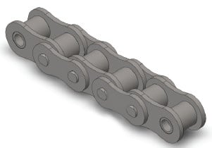 of input electrical power (electrical motor, inner combustion engine with mechanical or hydraulic drive).
? Type of products to get driven.
? Amount of horsepower essential to supply suffi cient power on the driven shaft.
? Full load velocity in the fastest working shaft (rpm).
? Desired speed in the slow working shaft ( or the essential pace ratio). NOTE: If speeds are variable decide the horsepower to get transmitted at every single velocity.
? Diameters on the drive and driven shafts . . . This worth may perhaps restrict the minimum variety of teeth for the sprockets.
? Center distance from the shafts.
? Note the position and any area limitations that could exist. Commonly these limitations are around the maximum diameter of sprockets (this restricts the usage of single strand chains) or even the width on the chain (this restricts the use of multi-strand chains).
? Conditions in the drive which include a determination of the class of load (uniform, moderate or heavy), severe working temperatures or chemically aggressive environments need to be mentioned.
Abbreviations Utilized in Equations
N Number of teeth to the massive sprocket.
n Amount of teeth within the modest sprocket.
R Pace in revolutions per minute (rpm) of your significant sprocket.
r Speed in revolutions per minute (rpm) of your little sprocket.
C Shaft center distance in chain pitches.
HP Horsepower rating on the drive motor or engine.
KW Kilowatt energy rating of drive motor or engine if utilizing metric units.
SF Support Factor
Any injury over the teeth surfaces of the sprocket diminishes the life of your conveyor chain.
With traditional sprockets, substantially worn sprocket teeth were repaired by teeth padding or even 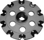 the total sprocket was replaced. In both case, fix was costly and with teeth padding, accuracy was impaired. We produced new sprockets with detachable teeth for independent substitute. This sprocket is highly rated by our shoppers for your dramatic financial savings in cost and time.
Framework
The teeth is often replaced by two approaches: personal tooth substitute or sectional teeth replacement.
The bolts and nuts applied for mounting the teeth on towards the sprocket are spot-welded to stop loosening.
The respective structures are illustrated around the appropriate.
The over photograph and also the leading appropriate illustration present a sprocket for person tooth replacement. Since the joint encounter in between the replaced teeth along with the sprocket is formed inside a distinctive arc, the bonding accuracy is substantial and the sprocket strength is enhanced. Furthermore, since the load acting over the mounting bolts is decreased, there exists significantly less chance of loosening. This sprocket development is patented.
You can find two styles of hubs: cast steel and welded sheet steel hubs. Cast steel hubs are used for large sprockets acquiring heavy loads and welded sheet steel hubs for other applications.
For Use at Low-temperature
When using conveyor chains at low-temperature this kind of as in the refrigerator  or in the cold ambiance, the following circumstances may perhaps come about.
one) Minimal temperature brittleness
Usually, a material is embrittled at low-temperature and shock resistance is lowered. This phenomenon is named low-temperature brittleness, as well as degree of embrittlement differs from materials to materials.
The services restrict of a conveyor chain relies on its specs.
two)Influence of freezing
At low-temperature, bending failure, roller rotation failure, fixing of chain, etc. could be brought about from the freezing of penetrated water or deposited frost while in the clearance among pins and bushings, bushings and rollers or inner plates and outer plates. These problems bring about an overload to act over the chain and drive, diminishing the lifestyle in the chain.
To stop freezing, usually, it can be suggested to fill the clearances by using a low-temperature lubricant ideal towards the support temperature to stop water, frost, and so on. from penetrating the respective portions of your chain. For lubrication, a silicon based grease is suggested.
For Use at High-temperature
Chains strength is diminished by high-temperature atmosphere, direct conveying of high-temperature loads, or radiated heat, and so forth. The support restrict at high-temperature depends not about the temperature with the support environment but the temperature and material of the chain physique.
Following ailments may well happen when chains are used at high-temperature:
1) High temperature brittleness and fracture by lowered hardness of heat handled material
2) Brittleness brought on by carbide precipitation
three) Abnormal dress in by scale
4) Fatigue fracture brought about by repeated thermal shock (cooling and growth)
5) Abnormal dress in on account of an increase during the coefficient of friction
6) Creep fracture
seven) Fracture as a consequence of thermal fatigue of welded location
eight) Effects caused by thermal expansion
?Stiff hyperlinks and rotation failure as a result of decreased clearance ?Fatigue fracture resulting from lowered fitting force
9)Lubrication failure and stiff links resulting from deterioration and carbonization of lubricating oil
Grease exceptional in heat resistance contain individuals based on silicon, graphite or molybdenum disulfide.
For use at high-temperature, high-temperature resistance bearings and stainless steel bearings are suggested.
Usually, a chain is bent in transverse course only. Nonetheless, a 3D Bending Conveyor Chain may be structurally bent not merely horizontally but additionally vertically. It’s utilised for any conveyor line which moves vertically and adjustments in path.
X Type Chains for Trolleys, and Power & Free Conveyors
X-type Chains are applied for trolleys, and electrical power & free conveyors. They are drop-forged rivetless chains featuring high strength, lightweight and easy removal of components. The bottom left photo shows an X-type Chain used as a trolley conveyor  with only one rail.
The bottom right photo shows an X-type Chain utilised for a energy & free conveyor. An additional rail is installed to receive the load for higher transfer capability.
A power & free conveyor generally has a so-called stop and go function to connect and disconnect conveyed materials with and from the chain, so that the conveyed materials could be temporarily stopped, mixed and stored.
Three kinds of X-type Chains are available according to required strength.
Z-type Chain for Light Load Trolley Conveyors
A Z-type Chain for trolley conveyors is utilised for service similar to that of X-type Chains described on the previous page, but is suitable for light loads. It really is widely employed in conveyors supplying parts, and devices for storing and unloading parts on automobile assembling lines.
Z-type Chain for Light Load Trolley Conveyors
A Z-type Chain for trolley conveyors is utilized for service similar to that of X-type Chains described on the previous page, but is suitable for light loads. It truly is widely utilised in conveyors supplying parts, and devices for storing and unloading parts on automobile assembling lines.
FH Style Chain for Freeyor
An FH Form Chain is made use of for the same purpose as an X-type Chain and Z-type Chain. While X-type Chain is designed for heavy loads and Z-type Chain is for light loads, FH Style Chain is made use of for intermediate loads. While X-type Chain and Z-type Chain can be vertically bent only slightly, FH-type Chain could be bent both vertically and horizontally, which makes it suitable to get a conveyor line moving vertically. We manufacture three kinds of FH-type Chains different in pitch.
Towline Low-Selec-Tow Chain
A towline conveyor has a mechanism to convey dollies caught by a chain buried in the floor. Our chain for towline conveyor is called LST chain (Low-selec-tow chain).
LST Chain is usually bent horizontally and can also move on a slight incline. It is actually made by forging, and a recess for hooking a dog is formed at the center of each link.
Chains utilised for collecting accumulated sediment in setting basins and sedimentation basins or getting rid of the collected sediment in sewage treatment facilities along with other water remedy amenities require in particular higher resistance to corrosion and put on because they may be right exposed to sewage and sludge. A filth getting rid of chain is moved at a comparatively quick speed on an nearly vertically installed rail, though the operation frequency is very low, so WS Type Roller Chain is utilised. Conversely, a chain for raking up and/or out dirt is driven at an exceptionally slow speed and doesn’t need rollers, so WAS Type Bush Chain is utilised.
Eighteen kinds of WS Form and six types of WAS Type Chain can be found.
(a) WS Sort Roller Chain
A WS Kind Roller Chain is created to provide  higher corrosion resistance and wear resistance for long support within the significant natural environment of water therapy applications.
Because the operating time of this type of equipment is comparatively short, pins and bushings of hardened stainless steel as well as other parts are created of particular alloy steel to guarantee smooth bending from the chain, and great dress in and corrosion resistance.
(b) WAS Form Bush Chain
Heat treated stainless steel provides this chain with outstanding effectiveness for corrosion resistance and dress in resistance.
BF Form Bushing Chain for Water Treatment method Drive Unit
This chain is used to connect water treatment tools to a electrical power source. Inside the previous, JIS/ ANSI type roller chains had been made use of. For enhanced corrosion resistance, all of the parts are now produced of 13Cr stainless steel. Because the chain is operated at a slow speed, a bushing chain devoid of rollers is made use of. The sprockets are interchangeable with JIS/ ANSI roller chain sprockets.
We manufacture 7 kinds of BF Form Bushing Chains inside a vary from 120 to 240, including heavy-duty kind.