General Description
Equiped that has a reversible motor, a bidirectional gear pump, double P.O. checke valves, relief valves in addition to a tank, this electrical power unit can drive a double acting cylinder to lengthen and retract without a directional solenoid valve. It can be generally utilized in recre-ational automobiles, pleasure boats and transportable phases, and so forth.
Distinctive Notes
1. This electrical power unit is of S3 duty cycle, i.e., non-continuous operation, 30 seconds on and 270 seconds off.
two. Clean each of the hydraulic components concerned in advance of set up of the 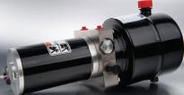 power unit.
three. Viscosity of your hydraulic oil shoud be 15~46 cst, which ought to also be clean and free of charge of impurities. N46 hydraulic oil is encouraged.
4. The electrical power unit proven is designed to be mounted horizontally.
5. Oil modifying is needed soon after the original a hundred operation hrs, afterwards as soon as every single 3000 hours.
six. Check the oil level within the tank soon after the initial operating in the power unit.
Archives
Power UNITS FOR LIFT TABLE 1
Standard Description
This power unit is created solely for your small lift table,Consisting of substantial strain gear pump, AC motor, multi-functional manifold, valves, tank, and so forth. This power unit is broadly made use of within the marketplace of logistic products such as minifork lift, scissors lift and ariel doing work platforms. The lower-ing motion is managed by the solenoid valve together with the pace controlled by the adjustable needle valve.
Electrical power UNITS FOR LIFT TABLE 2
General Description
This electrical power unit is designed exclusively for that medium lift table, Consisting of really effecient gear pump, AC motor, multifunctional manifold, valves, tank, ect. The decreasing motion is actived by the solenoid valve as well as the velocity controlled from the adjustable needle valve. When the lift rises to a large positoin, but the power supply is minimize, the decreasing movement is controlled from the manual override function.
Energy UNITS FOR LIFT TABLE three
Basic Description
This power unit is designed exclusively to the substantial lift table, Consisting of highly effecient gear pump, AC motor, multi-functional manifold, valves, tank, ect. The decreasing movement is actived from the solenoid valve and  also the pace managed by a strain compensated movement manage valve.
Power UNITS FOR LIFT TABLE 4
General Description
This power unit is designed solely for the massive lift table, Consisting of highly effecient gear pump, AC motor, multi-functional manifold, valves, tank, ect. The decreasing movement is actived by the solenoid valve and also the speed managed by the adjustable needle valve. Once the lift rises to a higher positoin, but the energy supply is lower, the reducing movement is controlled from the manual override function.
Special Notes
one. This power unit is of S3 duty cycle, which could only do the job intermittently and repeatedly, i.e. 1 minute on and 9 minutes off.
two. Clean all of the hydraulic parts concerned before set up of the power unit.
3. Viscosity of the oil shoud be 15~46 cst,which need to also be clean and free of charge of impurities.N46 hydraulic oil is proposed.
4. Oil shifting is needed immediately after the initial 100 operation hours,afterwards the moment just about every 3000 hours.
5. The power unit proven is built to be mounted vertically.
Power UNITS FOR DOCK LEVELER one
Standard Description
This Dock leveler energy unit simply just raised the ramp when the motor is activated, when the ramp has reached complete extension the sequence shifts to extend the lip. The ramp and lip are lowered by separate solenoid valves when the descent. Both the ramp and lip f of every functions are managed by a needle valve. The needle valves are adjustable to attain the wanted descent velocity of each perform.
Power UNITS FOR DOCK LEVELER 2
General Description
This Dock leveler power unit basically raised the ramp 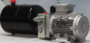 once the motor is activated, when the ramp has reached full extension the sequence shifts to extend the lip. The ramp and lip are lowered by separate solenoid valves when the descent. Each the ramp and lip f of every functions are controlled by a needle valve. The needle valves are adjustable to accomplish the sought after descent speed of each function.
Energy UNITS FOR DOCK LEVELER three
General Description
This Dock leveler energy unit only raised the ramp once the motor is activated, once the ramp has reached full extension the sequence shifts to extend the lip. The ramp and lip are lowered by separate solenoid valves although the descent. Each the ramp and lip f of every functions are managed by a needle valve. The needle valves are adjustable to achieve the desired descent velocity of each function. The 2nd relief valve guarantees the primary platform to become floating below load once the dock leveler is being used for loading and unloading the products, as a result guarding the dock leveler efficiently.
Standard Description
This power unit features a long lasting magnet motor which has a power up gravity down circuit. Activate the start out solenoid to start the motor to lift the machine. The lowing motion is activated through the solenoid valve using the reducing pace managed from the pressure compensated flow manage valve. Solutions of this series can be widely used in the sector of logistic units such 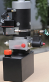 as fork lift, mini lift table, and so forth.
Unique Notes
1. This electrical power unit is of S3 duty cycle, i.e.,non-continuous operation, 30 seconds on and 270 seconds off.
2. Clean the many hydraulic elements concerned just before set up of the electrical power unit.
3. Viscosity on the hydraulic oil shoud be 15~46 cst, which must also be clean and free of impurities. N46 hydraulic oil is advisable.
4. This power unit is created to be mounted vertically.
5. Check the oil degree within the tank right after the 1st star in the energy unit.
6. Oil shifting is needed following the first 100 operation hrs,afterwards the moment every 3000 hours.
seven. More pump sizes and tank sizes are avaiable upon request.
Materials Dealing with Electrical power UNIT two
Standard Description
This power unit functions energy up gravity down circuit. Activate the get started solenoid to start out the motor to lift the machine. The lowing movement is activated from the solenoid valve with the decreasing speed managed through the pressure compensated flow control valve. Merchandise of this series might be extensively utilized in the marketplace of logistic gadgets like fork lift, mini lift table, and so on.
Distinctive Notes
1. The duty of this power unit is S3,i.e.,thirty seconds on and 270 senconds off.
two. Clean every one of the hydraulic components concerned in advance of mounting the energy unit.
3. Viscosity with the hydraulic oil shoud be 15~46 cst,which really should also be clean and cost-free of impurities, N46 hydraulic oil is proposed .
four. Oil modifying is needed after the first a hundred operation hours,afterwards once every single 3000 hours.
5. The energy unit ought to be mounted horizontally.
Materials Dealing with Energy UNIT one
Basic Description
This energy unit is made for that fork lift marketplace, consisting of extremely productive gear pump, DC motor, manual raise and lower valve, tank, ect. The up and down movement are controlled through the lever from the manual release valve, that is outfitted with an electric switch to activate the motor. The lowing speed is controlled through the pressure compensated flow manage valve.
Special Notes
one. The duty of this electrical power unit is S3, i.e. thirty seconds on and 270 senconds off.
two. Clean the many hydraulic parts concerned just before set up of 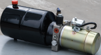 the power unit.
three. Viscosity on the hydraulic oil shoud be 15~46 cst, which should really also be clean and no cost of impurities, N46 hydraulic oil is proposed .
four. Oil altering is needed right after the initial a hundred operation hrs, afterwards as soon as every single 3000 hrs.
5. The power unit proven is built to be mounted horizontally.
Basic Description
Consisting of the stress balanced gear pump, DC motor, multi-functional manifold, valves, tank, ect., this electrical power unit is created to operate material managing products. The reducing motion is achived by the solenoid 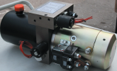 valve with the reducing velocity controlled by an adjustable needle valve. The left and appropriate functions are equipped using a dual pilot operated verify valve and cross-over relief valves.
Remark: Please seek the advice of our income engineer to the diverse pump displacement, motor energy or tank capability.
Exclusive Notes
1. This energy unit is of S3 duty cycle, i.e.,non-continuous operation,30 seconds on and 270 seconds off.
2. Clean all the hydraulic components concerned prior to set up of the power unit.
3. Viscosity from the hydraulic oil shoud be 15~46 cst, which must also be clean and free of charge of impurities.N46 hydraulic oil is proposed.
4. This energy unit need to be mounted horizontal.
5. Check the oil level in the tank soon after the primary start out with the electrical power unit.
six. Oil modifying is needed after the preliminary one hundred operation hrs, afterwards after just about every 3000 hrs.
DUMP TRAILER Power UNIT-DOUBLE ACTING
Common Description
This power unit has a energy up electrical power down circuit with load holding on the two A & B ports. A pressure compensatred movement management is usually added to circuit to control the decent speed of the cylinder.
Specific Notes
one. This electrical power unit is of S3 duty cycle, i.e., non-continuous operation, 30 seconds on and 270 seconds off.
2. Clean all the hydraulic elements concerned before installation of the energy unit.
3. Viscosity of the hydraulic oil shoud be 15~46 cst, which must also be clean and absolutely free of impurities. N46 hydraulic oil is encouraged.
4. The energy unit really should be mounted horizontally.
5. Check the oil degree within the tank immediately after the initial operating of the power unit.
6. Oil modifying is required soon after the preliminary one hundred operation hrs, afterwards when just about every 3000 hours.
DUMP TRAILER Energy UNIT- SINGLE ACTING
Basic Description
This energy unit includes a power up gravity down circuit. Start the motor to lengthen the cylinder and activate the solenoid valve to retract the circuit. Guide override to solenoid valve could be supplied if demanded. Also a pressure compen sated movement manage may be added towards the circuit to regulate the descent speed from the cylinder.
Remark: Please seek the advice of our product sales engineer for the various pump displacement, motor energy or tank capacity.
Particular Notes
1. This electrical power unit is of S3 duty cycle, i.e., non-continuous operation, 30  seconds on and 270 seconds off.
two. Clean every one of the hydraulic elements concerned prior to set up of the energy unit.
3. Viscosity on the hydraulic oil shoud be 15~46 cst,which really should also be clean and free of charge of impurities.N46 hydraulic oil is advised.
4. The power unit must be mounted horizontally.
five. Check the oil level while in the tank just after the first running in the energy unit.
6. Oil altering is required soon after the first a hundred operation hrs, afterwards the moment just about every 3000 hrs.
General Description
Equipped using the zero leak bidirectional checking sole-noid valves, this energy unit is built for that operation of two independent circuits. Which are respectively for your principal and subordinate platforms of the double scissors lift. Two cut-off valves are utilized for reducing the machine manually in situation of energy loss. If more independent circuits are required to your application please contact us for availability.
Remark: one. 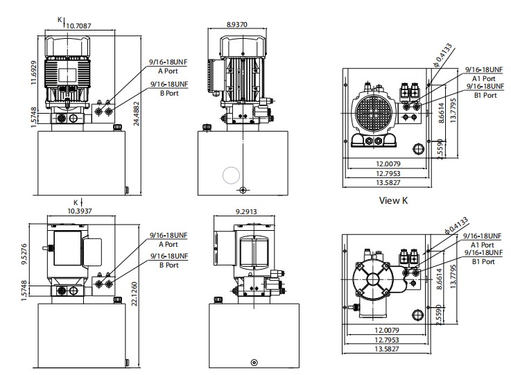 Please talk to our sales engineer for your distinctive pump displacement, motor electrical power or tank capacity.
2. CSA or UL certified motors can be found upon request.
Distinctive Notes
one. The AC motor is of S3 duty cycle, which may only work intermittently and repeatedly, i.e., 1minute on and 9 minutes off.
two. Clean all of the hydraulic components concerned in advance of installation of the energy unit.
3. Viscosity of the oil shoud be 15~46 cst,plus the oil really should be clean and free of charge of impurities,N46 hydraulic oil is advisable.
four. The power unit really should be mounted vertically.
5. Check the oil degree in the tank following the initial running of your power unit.
6. Oil shifting is required soon after the first one hundred operation hrs,afterwards once every 3000 hrs.
Introduction
A mindful assessment in the situations surrounding a conveyor is critical for accurate conveyor chain variety. This segment discusses the fundamental considerations necessary for prosperous conveyor chain assortment. Roller Chains are frequently utilized for light to moderate duty material handling applications. Environmental circumstances may perhaps call for using specific materials, platings coatings, lubricants or even the ability to operate without extra external lubrication.
Basic Data Required For Chain Variety
? Type of chain conveyor (unit or bulk) which includes the technique of conveyance (attachments, buckets, through rods and so on).
? Conveyor layout such as sprocket locations, inclines (if any) as well as the variety of chain strands (N) to be utilized.
? Amount of materials (M in lbs/ft or kN/m) and style of material for being conveyed.
? Estimated fat of conveyor components (W in lbs/ft or kN/m) together with chain, slats or attachments (if any).
? Linear chain speed (S in ft/min or m/min).
? Environment through which the chain will operate together with temperature, corrosion circumstance, lubrication problem etc.
Step 1: Estimate Chain Tension
Make use of the formula under to estimate the conveyor Pull (Pest) and then the chain stress (Check). Pest = (M + W) x f x SF and
Check = Pest / N
f = Coefficient of Friction
SF = Velocity Factor
Step two: Produce a Tentative Chain Assortment
Using the Test worth, produce a tentative choice by deciding on a chain
whose rated working load better compared to the calculated Test value.These values are proper for conveyor services and therefore are diff erent from these shown in tables in the front of your catalog which are related to slow pace drive chain usage.
Moreover to suffi cient load carrying capacity normally these chains must be of a selected pitch to accommodate a preferred attachment spacing. As an example if slats are to get bolted to an attachment each 1.five inches, the pitch of your chain selected have to divide into 1.5?¡À. Thus a single could use a 40 chain (1/2?¡À pitch) together with the attachments each and every 3rd, a 60 chain (3/4?¡À pitch) with the attachments each and every 2nd, a 120 chain (1-1/2?¡À pitch) with the attachments each pitch or maybe a C2060H chain (1-1/2?¡À pitch) using the attachments each and every pitch.
Stage three: Finalize Variety – Calculate Real Conveyor Pull
After building a tentative assortment we need to verify it by calculating
the real chain tension (T). To try and do this we will have to fi rst calculate the actual conveyor pull (P). Through the layouts proven about the ideal side of this page select the appropriate formula and determine the complete conveyor pull. Note that some conveyors can be a blend of horizontal, inclined and vertical . . . in that situation calculate the conveyor Pull at each and every area and add them with each other.
Stage four: Determine Greatest Chain Stress
The maximum Chain Tension (T) equals the Conveyor Pull (P) as calculated in Step 3 divided through the variety of strands carrying the load (N), times the Pace Issue (SF) shown in Table two, the Multi-Strand Issue (MSF) proven in Table 3 as well as the Temperature Component (TF) shown in 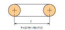 Table 4.
T = (P / N) x MSF x SF x TF
Phase 5: Test the ?¡ãRated Operating Load?¡À on the Selected Chain
The ?¡ãRated Functioning Load?¡À of your picked chain should be better than the Greatest Chain Tension (T) calculated in Step 4 above. These values are acceptable for conveyor support and are diff erent from those shown in tables with the front with the catalog which are related to slow velocity drive chain usage.
Stage six: Verify the ?¡ãAllowable Roller Load?¡À of your Picked Chain
For chains that roll over the chain rollers or on major roller attachments it is actually needed to check out the Allowable Roller Load?¡À.
Note: the Roller load is established by:
Roller Load = Wr / Nr
Wr = The total bodyweight carried through the rollers
Nr = The number of rollers supporting the fat.
Leaf Chains are manufactured for substantial load, slow speed tension linkage applications. Generally they are really specifi ed for reciprocating motion lifting gadgets this kind of as fork lifts or cranes. These chains are typically supplied to a specifi c length and therefore are connected to a clevis block at just about every end. The clevis may well accommodate male ends (inside or from time to time termed “articulating” back links) or female ends (outside or even the hyperlinks over the pin link) as needed (see illustration below)
Leaf chains are available in 3 series; AL (light duty), BL (heavy duty), or LL (European regular). For new selections we advise the BL series in preference to your AL series since the latter continues to be discontinued as being a acknowledged ASME/ANSI standard series chain. BL series chains are made in accordance with all the ASME/ANSI B29.8 American Leaf Chain Standard. LL series chains are generated in accordance together with the ISO 606 global leaf chain standard.
A chain with an even variety of pitches normally has a 1 male and one particular female finish. It is extra common to get the chain possess an odd quantity of pitches through which case the each ends will be both male (most common) or female (less com-mon). When ordering lengths with an odd amount of pitches male ends are supplied unless of course otherwise noted. Clevis pins, usually with cotters at every single finish, are utilized to connect male chain  ends to female clevis blocks. Chains with female ends tend to be (but not generally) connected on the clevis block having a cottered form connecting link. The connecting link is the female finish part in this case.
Leaf Chain Selection
Make use of the following formula to verify the choice of leaf chain:
Minimal Greatest Power > T x DF x SF
T: Calculated Maximum Chain Tension
DF: Duty Element
SF: Services Issue
Note that the greatest allowable chain pace for leaf chains is 100ft per minute.