The next data need to be presented to when placing an purchase to be sure the appropriate selection of the disc coupling:
Application and style of duty
Sort of driver (engine, motor, turbine, and so forth.)
Speed and horsepower
Variety of driven
Shaft sizes and separation
Room limitations for big diameter and length
Variety of fit (Interference fit default, clearance fit and shaft locking device preparation available upon request)
Special 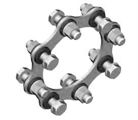 necessities (vertical mounting, drop out center, flange mount, electrically insulated, API-610 as much as three,800 RPM, shear pins, balancing, etc.)
Angular misalignment, axial misalignment, and rated torque are all associated for the coupling’s capacity to accommodate application torque above any period of time. As illustrated during the following charts, once the application torque increases to 50% from the coupling capacity, the potential from the coupling to accommodate angular misalignment to is decreased. The identical holds real for the ability to accommodate axial misalignment.
Selection Method
1. Select the coupling style.
two. Select the driven machine services factor SFA
3. Select the driving machine service factor SFD
Care really should be taken when the driving machine is apart from a regular electrical motor or turbine. Some engines will impose added fluctuations on the drive program and allowance need to be manufactured accordingly. A torsional coupling may well be demanded for diesel drives.
Category Archives: woodsdriveshaft
The next is usually a sample application employed to illustrate the standard approach for picking out a Disc coupling. Any resemblance to any current company?¡¥s application is neither intentional nor meant to resemble that company?¡¥s real application.
Sample Application:
An organization has a compressor application applying a 225 horsepower electrical motor operating at 1,150 RPM to drive a three cylinder multi stage reciprocating air compressor. The electrical motor has a 3-3/8 inch shaft with a 7/8 inch keyway and also the compressor includes a 92mm shaft using a 25mm keyway. The shaft separation is roughly 7 inches among shaft ends with some capacity to modify the motor spot. The shafts have a parallel misalignment/offset of approximately 1/32 of an inch.
Stage one: The very first phase is usually to decide what coupling variety should be to be chosen for this application. Because the SU Kind coupling only supports
a single flex plane, it might only accommodate angular and axial misalignment, but not parallel misalignment. The subsequent option will be to look at an SX or DI Sort coupling. The 6 bolt SX Kind will accommodate the two parallel misalignment along with the defined shaft separation. The size will likely be established from the selection torque along with the shaft diameters.
Phase 2: 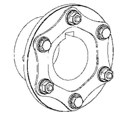 Next, calculate the application torque and apply the service issue to calculate the selection torque.The formula utilized to calculate torque is as follows:
Application Torque ( in¡§Clb ) = ( HP x 63025 )/RPM
or Nm = ( KW x 9550)/RPM
Plugging within the numbers through the application description:
Application Torque ( in-lbs ) =(HP x 63025)/RPM = (225 x 63025)/1150 = 12,331 in-lbs
Application Torque x Services Component = Choice Torque
12,331 in-lbs x three.0 = 36,993 in-lbs
Stage three: Utilize the SX coupling tables and note the SX 202-6 is rated at forty,700 in-lbs, over sufficient to manage the selection torque calculated in stage 2. The SX202-6, on the other hand, is not going to help the 92mm shaft dimension. The next bigger size coupling, the SX228-6, will help the 92mm shaft dimension plus the shaft separation dimension (BSE) is 6.88 inches, quite near to the application?¡¥s sought after 7 inch separation. The SX228-6 is rated at 62,000 in-lbs which may possibly appear to be extreme, nevertheless, the coupling dimension is necessary to deal with the bore dimension.
Stage four: The SX228-6 coupling is rated to get a highest unbalanced speed of three,400 RPM, in excess of adequate to support the application velocity of 1,150 RPM.
Phase 5: To determine if the coupling will deal with the parallel misalignment, make use of the trig perform of tan 1?? = offset allowed for 1 inch = 0.0174
Multiply the 0.0174 x the distance in between disc packs or ??S?¡¥ dimension from your table on web page D-13, or 5.50 inches.
The allowable parallel offset is 0.0174 x 5.50 = 0.096 inches. The utmost offset for the application is 1/32 inches (0.031), as a result this coupling can accommodate the parallel misalignment.
Note: It truly is usually proposed to try to install the coupling at roughly 20% of the allowable misalignment. For this coupling the installer need to endeavor to reach far better than 0.020 parallel misalignment on the time of set up. This will allow for the supplemental misalignment that can arise because the outcome of products settle and standard gear dress in.
Industrial SU Kind
The SU Sort coupling features a single flex plane with two hubs as well as a single disc pack. It can be suitable for angular and axial misalignment only. Two SU couplings are often combined using a shaft
to generate a floating shaft coupling. The shaft can be hollow for extended light excess weight floating shaft couplings.
Industrial SX Variety
This really is the normal coupling form that incorporates two hubs, a stock length spacer intended to meet business regular lengths, and two unitized disc packs. The coupling has two flex planes, one at each disc pack, permitting this coupling to accommodate parallel, angular, and axial misalignment with specified limits. The coupling is obtainable in six and eight bolt patterns and bore sizes up to 13 inches (330mm) to the largest size. Custom spacer lengths can be produced to meet special shaft separations expected for certain applications. The SX coupling may be fitted with overload bushings to protect the disc packs in more than torque circumstances and can act as an anti-flail device. SX couplings are assembled on the time of installation around the equipment the place the coupling will probably be in support.
Industrial DI Style
The DI Kind coupling includes a “Drop-In” spacer assembly that’s assembled with the factory. The coupling consists of two hubs as well as a spacer assembly comprising from the spacer, two unitized disc packs, and two guard rings. The disc packs are bolted towards the spacer and guard rings at the factory making use of the torque values advised by Lovejoy for that disc pack bolts. Using the hubs mounted to the shafts, the complete disc pack assembly is often “Dropped In” 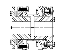 area between the two hubs. The hubs are piloted to be sure right centering of your spacer assembly. This piloting serves as an anti-flail feature and aids in the coupling’s potential to meet the stability standards mandated by API. This design coupling is designed to meet the stability and anti-flail necessities specified in API-610.
Oversized, or Jumbo, hubs are available for use with all the DI Variety coupling to allow for greater bore sizes on most DI coupling sizes. This allows for the use of smaller sized DI couplings in applications where a smaller size coupling can nonetheless accommodate the application torque.
Industrial SXC Variety
The SXC Sort is definitely the close coupled variation of the SX Form coupling. The SXC is much like the SX coupling in that the disc packs are connected when the coupling is set up. From the shut coupled units, the hubs are turned inward and are mounted within the spacer. Note that using the hubs inside the spacer, the utmost bore allowed during the hub is going to be decreased. The SXC couplings may be utilised with one or both hubs turned outward to permit the coupling to accommodate various shaft separations.
Industrial SXCS and SXCST Sorts
The SXCS and SXCST Varieties have split spacers plus the disc packs is often serviced or removed with no moving the hubs on the shafts and without the need of moving the products. The SXCS Type has the bolts that connect the hubs towards the split spacer set up from the ends with the couplings. The SXCST have the bolts set up from inside the spacer pointing outward in direction of the hubs.
Supplemental Types
Our disc packs are manufactured making use of large grade stainless steel
(AISI-301), making sure large strength, large endurance to fatigue, and resistance to most environmental disorders.
Disc couplings make use of unitized disc packs with the two six or 8 bolt models. The 8 bolt design can transmit greater torque than the six bolt style and design, having said that, it truly is not ready to accommodate as substantially angular misalignment.
Couplings can be fitted with overload bushings to protect the disc pack throughout momentary torsional overloads.
Couplings are offered within a assortment of configurations to match most applications. Furthermore, ?¡¥s engineering department can customize a coupling to meet many particular prerequisites such as near coupled, drop-out centers, electrically insulated, vertical mounting, and security couplings. A notable style and design provided by is definitely the lowered moment (DI Variety) coupling that meets the anti-flail gadget specifications mandated in API-610 when offering a very low fat and brief center of gravity to bearing distance.
The style and design and manufacture of disc couplings is integrated into a certified Top quality Program in accordance to ISO-9001 to fulfill the high excellent demands of consumers.
Strengths of the Disc Coupling
Eliminates the require for lubrication and coupling servicing
Coupling could be inspected with no disassembly
Condition of disc packs can be inspected with a strobe light even though the machine is operating
Note: It’s not advisable that couplings be operated devoid of coupling guards.
Easy to assess products misalignment
Torsionally rigid devoid of any backlash
No wearing components
\Resistance to harsh environments
Long lifestyle when effectively sized and aligned
High energy density (increased torque for a given outdoors diameter)
Supports the API-610 Standard up to 3,800 RPM
Unitized disc packs make certain repeatability needed for meeting the balance and piloting necessities as mandated by API-610
Available with Overload Bushings to safeguard the coupling from momentary torque overloadsPrevents the disc pack from staying plastically deformed
Allows for shorter BSE (shaft separation) simply because bolts could be turned to encounter inward
Special orientation of bolts enables the bolts to become tightened utilizing a torque wrench as an alternative to nuts (Regular is usually to tighten nuts with torque wrench)
The next headings include info on critical aspects for variety and proper use of gearbox.
For specific information about the gearbox assortment,see the related chapters.
1.0 OUTPUT TORQUE
one.1 Rated output torque
Mn2 [Nm]
The torque that will be transmitted constantly as a result of the output shaft, using the gear unit operated below a services element fs = one.
1.two Necessary torque
Mr2 [Nm]
The torque demand based mostly on application necessity. It truly is advised to get equal to or much less than torque Mn2 the gearbox below examine is rated for.
one.three Calculated torque
Mc2 [Nm]
Computational torque worth to become utilized when picking out the gearbox.
It is actually calculated contemplating the expected torque Mr2 and service issue fs, as per the partnership right here immediately after:Mc2 = Mr2 ?¡è fs ?¨¹ Mn2
two.0 Energy
2.one Rated input electrical power
Pn1 [kW]
The parameter 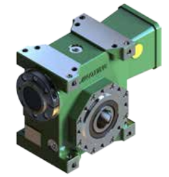 can be observed in the gearbox rating charts and represents the KW that can be safely transmitted towards the gearbox, primarily based on input pace n1 and service factor fs= 1.
two.2 Rated output electrical power
Pn2 [kW]
This value could be the electrical power transmitted at gearbox output. it could be calculated using the following formulas:
Pn2 = Pn1 ?¡è |?d
Pn2= Mn2*n2/9550
3.0 EFFICIENCY
Efficiency is usually a parameter which includes a big influence to the sizing of sure applications, and generally is determined by gear pair designelements. The mesh information table on page 9 displays dynamic efficiency (n1=1400)and static efficiency values.
Bear in mind that these values are only attained following the unit has become run in and it is at the functioning temperature.
3.1 Dynamic efficiency
[|?d]
The dynamic efficiency is definitely the romantic relationship of power delivered at output shaft P2 to electrical power utilized at input shaft P1:
|?d =P2/P1
three.2 Static efficiency[|?s]
Efficiency obtained at start-up of your gearbox. Whilst that is typically not sizeable aspect for helical gears, it might be as a substitute vital when deciding on worm gearmotors working beneath intermittent duty.
4.0 Support Component
The support factor (fs ) depends on the operating disorders the gearbox is subjected towards the parameters that have to be taken into consideration to select one of the most satisfactory servies component appropriately comprise:
1. type of load on the operated machine : A – B – C
two. length of day-to-day operating time: hours/day(?¡Â)
three. start-up frequency: starts/hour (*)
Variety of LOAD: A – uniform,fa?¨¹0.3
B – reasonable shocks, fa?¨¹3
C – hefty shocks, fa?¨¹10
fa=Je/Jm
–Je(kgm2) moment of your external inertia reduced at the drive shaft
–Jm(kgm2) moment of inertia of motor
–If fa>10 please contact our Technical Support
A -Screw feeders for light elements, supporters, assembly lines, conveyor belts for light components, smaller mixers, lifts, cleansing machines, fillers, control machines.
B -Winding devices, woodworking machine feeders, goods lifts, balancers,threading machines, medium mixers, conveyor belts for hefty components,winches, sliding doors, fertilizer scrapers, packing machines, concrete mixers, crane mechanisms, milling cutters, folding machines, gear pumps.
C -Mixers for hefty resources, shears, presses, centrifuges, rotating supports, winches and lifts for heavy products, grinding lathes, stone mills, bucket elevators, drilling machines, hammer mills, cam presses, folding machines, turntables, tumbling barrels, vibrators, shredders.
JDLB series higher precision worm gear is definitely an great substitute for precision planetary gearbox,the products manufacturer can substantially minimize the expense of employing precision planetary gearbox .Hollow output with shrink disc, high precision , for straightforward integration.Output with keyway, convenient installation, effortless integration.Sound shaft output (single, double ), higher stiffness, traditional solution.The designer’s ideal alternative is to rotate 90 degrees to put in the servo motor drive techniques.Worm shaft in series is often driven by 1 motor to accomplish synchronous output of a number of worm wheels. It’s been used in automatic polishing cell phone shell along with other equipments.
Optimized get hold of pattern
Superior processing technology and precision assembly to ensure the proper meshing from the tooth and reduce get hold of tension in the tooth surface
Special worm wheel bronze alloy makes the teeth have substantial power and good put on resistance.
That has a large ratio of tooth surface speak to, worm wheel is not uncomplicated to dress in , it could maintain the locked backlash .
Optimized adjustment structure
Immediately setting backlash
Greater stiffness and precision
Patent structure
Worm shaft employing Taper roller bearings
Installed two taper roller bearings with which have longer services lives.
Eliminates worm shaft alignment troubles
Bearing pre-tight set up, with increased help stiffness
Maintenance cost-free
Large functionality synthetic lubricant
Closed framework, no have to have to replace lubricant oil.
Promptly install servo motor
Higher stiffness and very low inertia coupling for servo motor
A range of flanges might be matched with the servo motor
Installed two taper roller bearings with which have longer services lives.
Eliminates worm shaft alignment issues
Bearing pre-tight installation, with higher help stiffness
Output torsional backlash available in two ranges:
Ultra precision: one arc minute for that most demanding applications
Precision: 2 to 4 arc minutes an excellent compromise cost and excellent
Housing with gravity casting
Substantial power Aluminum Alloy casting and heat remedy
Superior rigidity and low weight
Lovely shape and Great climate resisting property
Machine Form
one.Conveyors
Common lndustnes :
Sand & Gravel, Animal Feeds,Water Treatment,Agriculture,Quarrying,Baggage Handing,Baggage Handing,Port Authorities,Post & Parcel,Grain Dryers
Application Example :
1.Head drum drive for stcreen 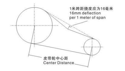 feeder.
2.Main drive on are inclined basalt conveyor.
3.Ship loading elevator.
4.Main drive to screw conveyer.
5.Overland buck conveyor drives.
6.Main drive for transporting animal floods.
7.Airport baggage handling conveyors
2. Mixers & Mills
Typical lndustnes : Animal,Feeds,Food,Industry,Agriculture,Petrochemical,Paint,Process,Industries,Aerators
Application Example :
1.Biscuit dough mixer
two.Main drive to animal feel mill
3.Main drive for Asphalt agitator
4.Paddle drive on animal feed processing piant.
3. Other Applications
Common lndustnes:
Cranes & Hoists,Winches,Tanning & Processing ,Textile Machinery,Laundry Machines,Machine tools,shears,etc.
Application Example:
1.Reversing duty on an industrial washing machine.
2.Container liftlng equipment.
3.Driven by an air motor on an under water winch system.
4.Wind turbine drive-used as speed increasing drive to generate electricity.
Method of Belt Tensioning
one. Calculate the deflection distance in mm on the basis of 16mm per meter of span. Center distance(m) x 16=Defection(mm).
two. Use a spring balance and rule measure the force of your belt, in the event the worth falls within the values offered, the drive ought to be satisfactory. Othewise, use the Torque arm’s turnbuckle adjust the tension in the belt. (Note, the force course along with the belt really should be a ideal angle).
SMR Gearbox Set up
Satisfactory efficiency depends on proper set up. lubrication and upkeep. hence it is necessary the guidelines during the set up and upkeep leaflet. supplied with each and every gearbox. are followed thoroughly. some of the crucial facets of belt and torque-arm installation are listed under.
1. Install pulley on gearbox input shaft as shut to your reducer doable, and mount reducer on driven shaft as near to bearing as sensible. failure to carry out this will likely trigger extra loads in the input shaft bearings and output 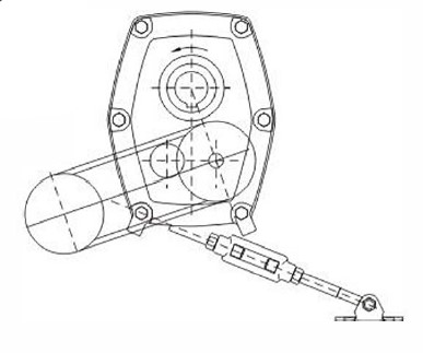 bearings and could trigger their premature failure.
2. Install motor and wedge belt drive using the belt pull at about 90° on the center line between driven and input shafts. this will permit tensioning with the wedge belt drive using the torque arm which should preferably be in stress. if output hub runs anti-clockwise. torque arm should be positioned the correct.
three. lnstall torque-arm fulcrum on a rigid support to ensure the torque-arm are going to be at somewhere around ideal angles on the center line with the driven shaft plus the torque arm case bolt. ensure that there is certainly ample get up during the turnbuckle for belt stress adjustment.
Maintain shut.
Bell drive could be located in any convenient postion. if your torque arm would be to be used to tighten the belts, the drive need to be at about tight angle to the line in between the input and output shafts.
Bell drive may very well be found on the proper if sought after.
If output hub rotates clock-wise. position belt drive and torque arm in opposite route to that proven while in the illustration.
Torque arm and belt get up.
Torque arm could possibly be mounted on the correct if sought after.
how you can purchase the SMR gear box
Gearbox Coding
Gearbox coding
To start with three letters: SMR
Fourth letter, unit size: BCD EFG HJ
Fifth and sixth digits, ratio code: 05 13 20
Seventh digit. indicates assembly: O shaft mounted velocity reducer 2 flange mount
Eighth digit: signifies output hub bore demanded: 1 standard metric bore. two different metric bore.
Illustration
Dimension e unit twenty:one nominal gear ratio, shaft mounted with common metric hub bore (55mm): SMR-E2001
It backstop are necessary, these must be order separately. and need to specify the output hub rotation. 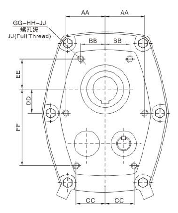 E.g.: SMR-E2001 comprehensive with backstop. from the input shaft side, the output hub’s rotation is in clockwise.
optional Extras
Backstops
A backstop may well be integrated on applications where it really is essential to reduce reversal of rotation. it truly is speedily installed inside the reducer, by only getting rid of a cover plate
Note: For ratio 5: one gear box, backstop will not advisable.
Flange mounting
SMR case style and design is such that the reducer is often bolted direct to supporting framework. this flange mounting use of the reducer may well permit designers to omit a bearing or pillow block, nevertheless it does. of course. remove the uncomplicated belt adjustment characteristic characteristic of shaft mount.
Note: Conventional SMR gearbox never drill mount screws. when consumer will need these sorts mount, please specify in the order.
Shaft Mount Reducer are metric in style and design all through and also have power ratings to AGMA common. Shaft Mount Reducers deliver an incredibly convenient method of lowering velocity, since it is mounted directly on the driven shaft as opposed to requiring foundations of its very own. It eliminates using 1, and occasionally two, flexible couplings and external belt take-up arrangements, A torque-arm anchors the reducer and delivers speedy, simple adjustment from the Wedge Belts by way of its turnbuckle.
Shaft Mount Reducers are manufactured in eight gear case sizes, nominal gear ratios are five:1, 13: one and 20: 1, A very wide alternative of ultimate driven speeds is usually established through the utilization of an appropriate input Wedge Belt Drive.
The units will normally be oil lubricated, but they are equally suitable for extended daily life synthetic lubricants.
Ascertain the output pace of the gear units, multiply the absorbed power (or Motor energy if absorbed power nit known) from the service component chosen in phase one.
Note: Gear units are momentarily capable of transmitting twice (2X) the rated capacity on commence or for the duration of operation.
Unit selection
The decision of single or double reduction gearbox will be established through the output pace demanded . The regular operating speeds for each of the gearboxes could possibly be observed within the energy rating and belt drive tables.
Note : When use five:1 Gear Units, the Back halt do not suggested.
choice of related belt drive for 1440 rpm electrical motors
1.0utput Speed
Refer for the Drive Variety Tables and below the appropr-late gearbox size and ratio go through down the column headed ‘Output Speed’until an Output Velocity equal or close to to that needed is discovered. The suggested gearbox ratio is given within the to start with column
2.Pulley Diameters
Study across from your chosen output speed to get both driving and drives pulley pitch diameters, groove segment and the proper number of belts.
Note: in lots of circumstances 1 belt is recommended, currently being sufficient for power transmission purposes
three.Center Distance
Belt length and center distance may be discovered by referring to the appropriate pages on the “Wedge Belt Drives” catalogue.
Variety of linked belt for driving speeds aside from 1440 rpm
one.Gearbox input Shaft Pace
Multiply the gearbox output velocity by the Precise GEAR RATIO to obtain the gearbox input shaft speed.
2.Choice of’V’ Drive
The right belt drive can now be picked referring to the’wedgr Bely Drives’ catalogue.