
Canada PTO driveline selection
Torsionally Resilient PTO Joint GE
The GE joint is an application-specific torsional element rather than a generic substitute for every clutch. Selection requires an understanding of inertia, start-stop behaviour, pulsating torque, resonant speed zones and the driveline layout.
Catalogue-exact data separated from engineering interpretation
Request an engineered selection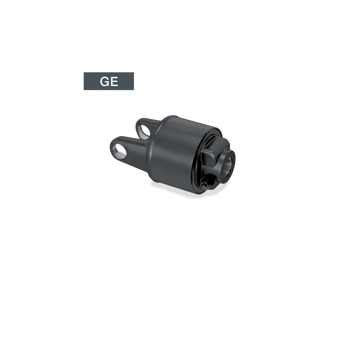
GEEvidence source
Catalogue page 14Market focus
Canada agricultural machineryOrder control
Approved drawing required
Catalogue technical data
Published family facts and source boundary
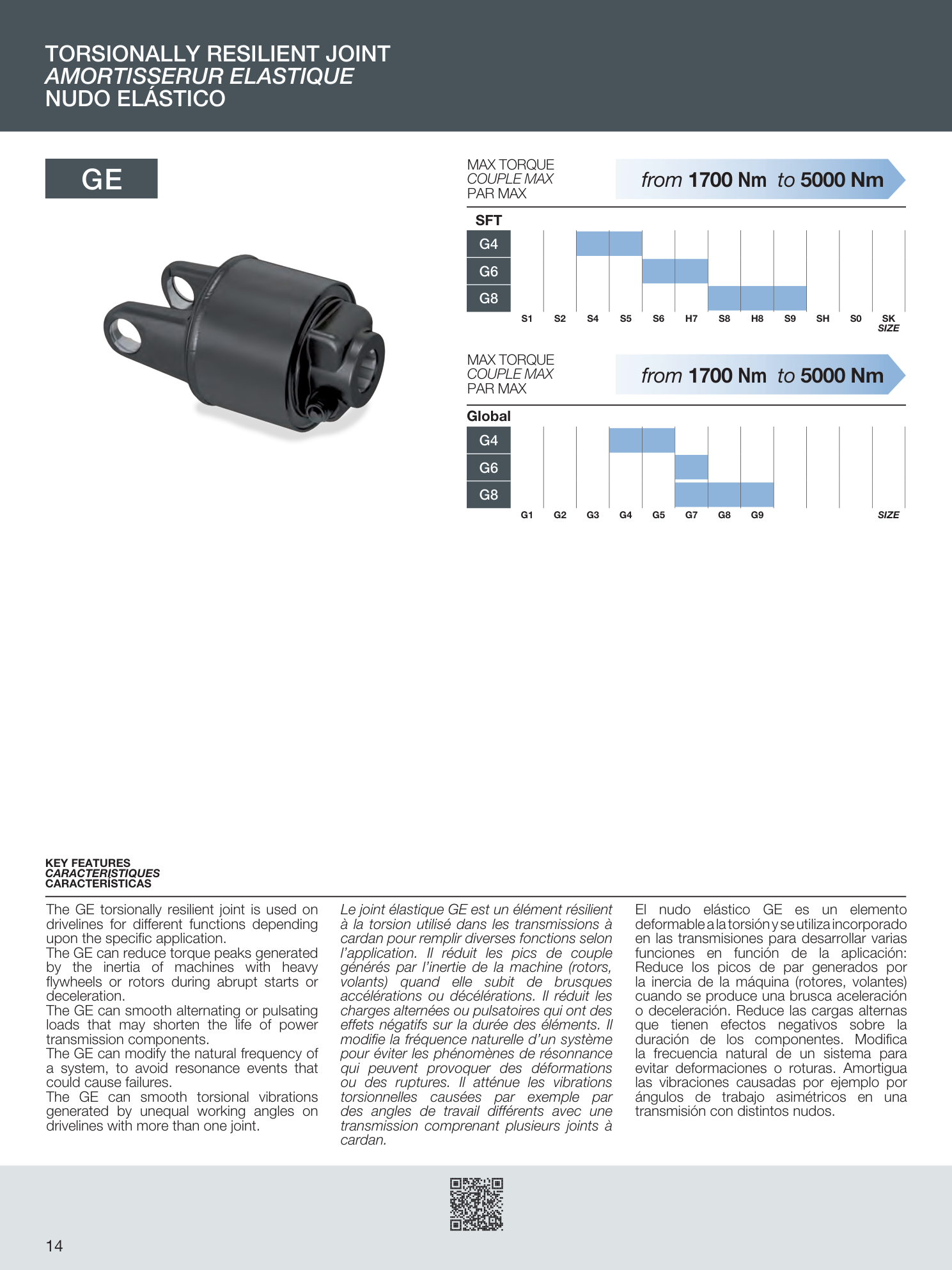
| Published maximum-torque range | From 1,700 Nm to 5,000 Nm |
|---|---|
| Function | Reduces torque peaks and alternating or pulsating loads |
| System effect | Can modify natural frequency to avoid resonance |
| Vibration control | Can smooth torsional vibration from unequal working angles |
| Compatibility | SFT and Global matrices are shown |
How to read the family data
The GE joint is an application-specific torsional element rather than a generic substitute for every clutch. Selection requires an understanding of inertia, start-stop behaviour, pulsating torque, resonant speed zones and the driveline layout.
Engineering interpretation: A resilient joint can change system dynamics. Without a duty-cycle and torsional assessment, moving the natural frequency may solve one operating condition but create another problematic speed range.
Torsionally Resilient PTO Joint GE is presented here as an engineering-selection family for implements with heavy flywheels or rotors, abrupt acceleration, cyclic loads or known torsional vibration. The catalogue image and table establish the published family envelope, but they do not identify a complete orderable assembly by themselves. A working PTO driveline is a system: tractor PTO interface, implement input connection, cross and bearing size, telescoping profile, compressed length, extension, operating angle, guard geometry and any clutch or limiter must all work together.
The GE joint is an application-specific torsional element rather than a generic substitute for every clutch. Selection requires an understanding of inertia, start-stop behaviour, pulsating torque, resonant speed zones and the driveline layout. The starting point should be the actual machine geometry. Measure the distance from the tractor PTO locking point to the implement input locking point at the shortest and longest positions of the hitch. Record the normal working angle and the maximum transient angle during lifting, lowering and turning. Those dimensions determine whether the tubes retain adequate overlap without bottoming or separating.
A resilient joint can change system dynamics. Without a duty-cycle and torsional assessment, moving the natural frequency may solve one operating condition but create another problematic speed range. The same nominal horsepower can create very different driveline stress depending on speed and load shape. A smooth centrifugal load, a reciprocating pump, a rotor with high inertia and an auger that jams all impose different peak torques. For this reason, the requested power should be accompanied by speed, normal torque, peak torque, starts per hour and any reversal or blockage event.
How to define the interfaces
Photographs are useful for orientation, but the RFQ should include measurable interface data. On the tractor side, state the PTO spline size, spline count, speed and locking method. On the implement side, state the shaft or spline specification, groove position, yoke or flange type and any clutch mounting constraints. When replacing an existing shaft, also record cross-kit cap diameter, cross span, tube profile dimensions and the fully compressed cross-to-cross length.
Do not assume that two visually similar yokes are interchangeable. Small differences in spline form, groove position, pin diameter, flange pilot or yoke ear spacing can prevent assembly or reduce engagement. Where an OEM part number is supplied, it is used only as a reference to locate the machine configuration; the approved drawing controls the replacement.
Length, overlap and hitch movement
A PTO shaft must remain short enough to avoid bottoming at the minimum tractor-to-implement distance and long enough to preserve safe telescoping engagement at the maximum distance. Bottoming can transmit axial load into tractor or implement bearings and can bend the shaft or damage the gearbox. Insufficient overlap reduces torsional capacity and can allow separation. The selection therefore uses measured minimum and maximum working distances, not the overall length of a removed shaft in an unknown position.
Check the entire motion envelope: three-point hitch raised and lowered, drawbar turns, transport position, headland steering and any sliding drawbar or articulating hitch. Guard cones, chains and clutch housings also need clearance. A shaft that is dimensionally correct in a straight static position can still contact the hitch or bottom during a sharp turn.
Angle and speed relationship
Universal-joint angle affects speed fluctuation, bearing motion and service life. Equal joint angles in a correctly phased conventional shaft help cancel the non-uniform motion created by each joint. If the angles are unequal, the implement input can accelerate and decelerate twice per revolution, producing vibration and cyclic torque. A constant-velocity head is used when the geometry requires powered turning beyond the practical range of a conventional arrangement, but its displayed maximum articulation remains a brief manoeuvring condition unless the approved data state otherwise.
Always identify whether the machine operates at 540 or 1000 rpm. At the same power, torque changes with speed, and the acceptable angle and balancing requirement can also change. Never use a power chart without confirming which speed curve applies.
Protection device strategy
The driveline may need an overrunning clutch, shear bolt, ratchet limiter, friction clutch or torsionally resilient element. These devices solve different problems. An overrunning clutch isolates coast-down inertia; it does not necessarily limit overload torque. A shear bolt gives a clear sacrificial release but requires the correct replacement fastener. A ratchet limiter automatically re-engages after an obstruction clears. A friction clutch limits torque by controlled slip and needs a verified setting and maintenance procedure. A resilient element modifies torque peaks and system dynamics.
Selection begins by describing the failure mode to prevent. Is the risk a one-time jam, repeated intermittent blockage, high-inertia start, reverse rotation, coast-down back-driving or torsional vibration? The answer determines the device type before the torque setting is chosen.
Guarding and operator safety
Every rotating part must be shielded as an integrated system: tractor master shield, driveline guard and implement input shield. The guard must rotate freely relative to the shaft and be restrained with the specified chains or retainers. Damaged, missing or modified guards must be replaced before use. The website imagery is a selection reference and does not replace the machine-specific risk assessment, local regulations, operator training or the equipment manufacturer instructions.
Before connecting, shut down the power source, prevent unexpected movement and confirm the PTO is disengaged. Keep clothing, hair and body parts away from rotating equipment. Never step over a connected shaft. Guard condition should be part of every pre-use inspection.
Installation and commissioning
Clean the mating splines and verify full locking engagement at both ends. Confirm shaft phasing, correct orientation of any CV head or overrunning device and adequate telescoping movement. Move the hitch slowly through its full range with the PTO stopped. Verify that the shaft does not bottom, separate or contact the drawbar, hitch, guard or implement frame. Lubricate every required point before first use because shipping protection is not necessarily an operating charge.
During the first powered test, start at low speed and no load where the machine procedure permits. Watch for guard movement, unusual sound, vibration, heating or axial movement. Stop immediately if the shaft whips, a guard contacts surrounding structure or a limiter cycles unexpectedly. Recheck fasteners and locking devices after the initial run.
Maintenance planning for Canadian service
Seasonal equipment in Canada can be exposed to condensation, road salt, fertilizer, wash water, mud and long storage periods. The catalogue interval is the starting reference for the documented family, but actual lubrication frequency must be shortened for wet, corrosive, dusty or continuous-duty service. Grease should purge contaminants from cross bearings and reach the telescoping profile where specified. Wipe fittings before greasing so dirt is not forced into the bearing.
Inspect guard tubes and cones, cross-bearing play, yoke cracks, tube dents, missing balance weights, spline wear, locking pins, chains, welds and fasteners. Free and reset friction clutches according to the approved procedure before the working season. Store the shaft supported, clean and protected from water entry; do not leave its weight hanging from a guard chain.
Failure diagnosis
Vibration can come from unequal angles, incorrect phasing, bent tubing, loose pilots, worn cross bearings, inadequate lubrication, excessive speed or operating near a structural or torsional resonance. A hot cross bearing suggests lubrication loss, excessive angle or overload. Twisted tube profiles indicate torque beyond the shaft capacity or an implement jam. A repeatedly sheared bolt or cycling limiter is a symptom that needs investigation, not a reason to fit a stronger unapproved component.
Record when the symptom occurs: straight running, turning, raising the hitch, start-up, full load or coast-down. This operating context helps separate geometry problems from overload, balance or resonance issues.
RFQ and drawing-approval checklist
- Machine make, model, year and implement function.
- Tractor PTO speed, spline and locking method.
- Implement input shaft or flange dimensions and rotation direction.
- Power, normal torque, peak torque and duty hours.
- Minimum and maximum cross-to-cross distance through the full hitch movement.
- Normal and maximum operating angle, including turning.
- Required clutch, limiter or overrunning function and current setting if known.
- Environmental exposure, storage pattern and lubrication access.
- Photos, existing part markings, cross dimensions and approved drawing where available.
Unknown values are not replaced with estimates in the quotation. They are listed as open points for engineering confirmation. Final manufacturing dimensions, materials, heat treatment, balance requirement, guarding and performance are controlled by the approved technical document.
Buyer evaluation themes
These are not fabricated product reviews. They summarize recurring evaluation priorities used on EVER-POWER/HZPT-style industrial inquiries and are presented as procurement themes rather than named testimonials.
The buyer wants the selection to be based on an application data sheet rather than a visual match alone.
The buyer expects drawings, interface dimensions and the approved configuration to control production.
The buyer values clear communication about what is catalogue-stated, what is derived and what still requires engineering confirmation.
Frequently asked questions
Can the shaft be selected from horsepower alone?
No. Power is only one input. Speed, torque, operating angle, compressed and extended length, telescoping overlap, end interfaces, duty cycle, overload behaviour and guarding all affect the selection.
Do you claim direct interchangeability with an OEM model?
Only after dimensional and functional verification against an approved drawing or sample. A similar series name or power envelope is not enough to prove interchangeability.
What information should be sent with an RFQ?
Provide tractor PTO speed and spline, implement input interface, required compressed length, working extension, normal and maximum angle, power or torque, duty hours, overload events, rotation direction, environment and photos or drawings.
Are catalogue values final production guarantees?
The catalogue is a selection reference. The approved quotation, technical data sheet and order drawing govern the supplied configuration.
Engineering RFQ
Send the operating data, not only a photo
For a reliable selection, include PTO speed, tractor and implement connections, compressed length, required extension, normal and maximum angle, power or torque, duty cycle and the required protection device.
Email: [email protected]
Canada correspondence address: 10990 Hogarth Dr, Richmond, BC V7E 3Z9, Canada